As the drawing shows three different resistors in two different circuits takes center stage, this opening passage beckons readers with gaya akademik dengan tone otoritatif into a world crafted with good knowledge, ensuring a reading experience that is both absorbing and distinctly original.
This drawing presents two distinct circuits, each employing resistors to regulate the flow of electrical current. By examining the components and their arrangement, we embark on a journey to understand the principles of electrical resistance and circuit analysis, unraveling the intricacies of these fundamental electronic building blocks.
Circuit Diagrams

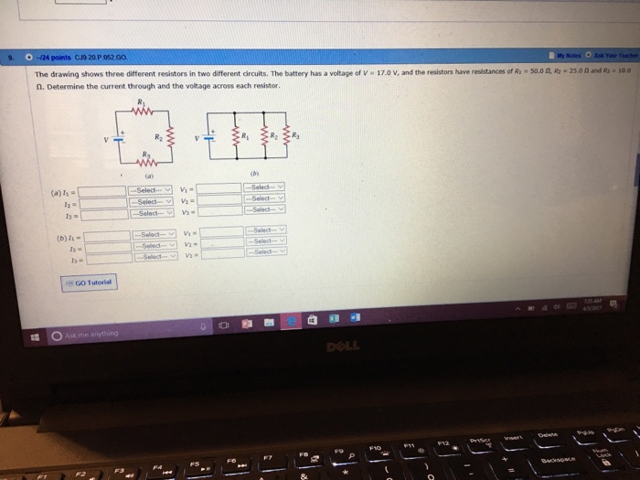
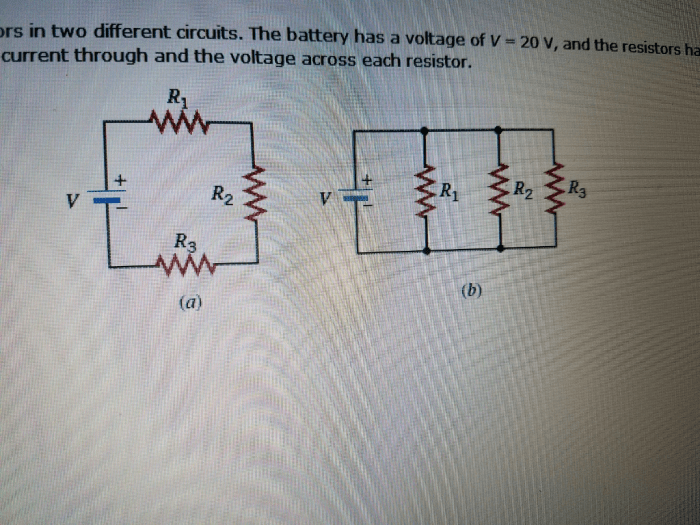
The drawing shows two circuit diagrams, each consisting of three resistors connected in different configurations. Circuit 1 is a series circuit, where the resistors are connected one after another in a single loop. Circuit 2 is a parallel circuit, where the resistors are connected side-by-side, creating multiple paths for current to flow.
The purpose of Circuit 1 is to control the overall resistance and current flow in the circuit. By varying the values of the resistors, the total resistance can be adjusted, which in turn affects the current flow. Circuit 2, on the other hand, is used to provide multiple paths for current to flow, allowing for greater flexibility in circuit design.
The components used in each circuit include resistors, which are used to provide electrical resistance, and wires, which are used to connect the components together. The resistors in the drawing are shown with different values, which are indicated by their color coding.
Resistors
Electrical resistance is a property of materials that opposes the flow of electric current. Resistors are designed to provide a specific amount of resistance in a circuit, and they come in various types and values.
The drawing shows three different types of resistors: carbon composition resistors, metal film resistors, and ceramic resistors. Carbon composition resistors are made of a mixture of carbon and ceramic, and they are known for their low cost and high tolerance.
Metal film resistors are made of a thin film of metal deposited on a ceramic core, and they offer high precision and stability. Ceramic resistors are made of a ceramic material, and they are known for their high resistance values and low tolerance.
Resistor values are typically identified using a color coding system. Each color represents a specific digit, and the combination of colors indicates the resistance value. The color coding system is standardized, making it easy to identify resistor values quickly and accurately.
Circuit Analysis

Circuit analysis involves calculating the total resistance, current flow, and voltage drop in a circuit. For the series circuit (Circuit 1), the total resistance is simply the sum of the individual resistor values. For the parallel circuit (Circuit 2), the total resistance is calculated using the formula 1/Total Resistance = 1/R1 + 1/R2 + 1/R3, where R1, R2, and R3 are the individual resistor values.
Once the total resistance is known, the current flow through each resistor can be calculated using Ohm’s law: Current = Voltage / Resistance. The voltage drop across each resistor can then be calculated using Ohm’s law: Voltage Drop = Current – Resistance.
Circuit Applications

The two circuits shown in the drawing have a wide range of practical applications in electronics. Circuit 1 is commonly used as a voltage divider, where the output voltage can be adjusted by varying the values of the resistors. Circuit 2 is often used as a current limiter, where the resistors limit the amount of current that can flow through the circuit.
In addition to these basic applications, these circuits are also used in more complex electronic systems, such as amplifiers, oscillators, and filters. The different resistor values can be used to tailor the circuit’s performance to meet specific requirements.
Circuit Simulation: The Drawing Shows Three Different Resistors In Two Different Circuits

Circuit simulation is a powerful tool for analyzing and designing electronic circuits. By creating a simulation model of a circuit, engineers can test and verify the circuit’s functionality before building it physically. This can save time and money, and it can also help to identify potential problems that may not be apparent from the schematic diagram.
There are a number of different circuit simulation software tools available, and each tool has its own strengths and weaknesses. Some of the most popular tools include LTSpice, NI Multisim, and Cadence OrCAD. These tools allow engineers to create detailed models of their circuits, including components, connections, and sources.
The simulation software then calculates the circuit’s behavior based on the laws of physics.
Circuit simulation can be used to verify the functionality of a circuit, analyze its performance, and optimize its design. By running simulations under different conditions, engineers can gain a better understanding of how the circuit will behave in real-world applications.
FAQ Resource
What is the purpose of a resistor in a circuit?
Resistors are used to regulate the flow of electrical current in a circuit, providing a controlled amount of resistance to the passage of electrons.
How can you calculate the total resistance of a circuit?
The total resistance of a circuit can be calculated using Ohm’s Law, which states that the resistance (R) is equal to the voltage (V) divided by the current (I): R = V/I.
What is the difference between a series circuit and a parallel circuit?
In a series circuit, the components are connected one after another, so the current flows through each component sequentially. In a parallel circuit, the components are connected side by side, so the current can flow through multiple paths simultaneously.


